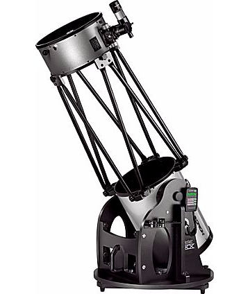
 I have a 14″ Dobsonian telescope made by Orion. It works well and has been fun to use, but I’d really like to do some astrophotography with it, and Dobsonian mounts aren’t suitable for that. Even driving both motors (altitude and azimuth) the field of view still rotates, so long exposures aren’t feasible.
An equatorial mount would solve the problem. Such a mounting has one axis parallel to Earth’s, and by adjusting around that axis only at the right speed you can keep the telescope in a precisely fixed orientation with respect to your target. No commercial mount exists for my scope, and if one did it would be prohibitively expensive. So some engineering is in order. After pondering on it for a while I decided I could pull it off. I’m going to document the process here; I imagine there are a lot of people who might like to make oen for themselves.
Basic Considerations
The Dobsonian mount has one axis vertical – that “big circle” at the bottom will rotate. It also has a horizontal axis that the scope is tipped around in the photo. By moving it around both of those axes in an appropriate way you can aim it at anything you like. For this project, our goal is to make the vertical axis point at the North Star (well, the North Star isn’t precisely at the celestial pole, but it’s close). For my location (Houston Texas area) that’s about a 60 degree tip. If I lived at the North or South Pole, it would work as is; close to one of the poles I could just put it as is on a wedge-shaped block. But 60 degrees is a big angle, and the existing mount isn’t structurally sound for that. So I’ll be dispensing entirely with the existing mount and making something new.
I decided to break the work into two parts: 1) a “base” that supports everything and provides a rigid shaft pointed at roughly the right angle, with adjustment capability to make that angle precise, and 2) a “fork” that mounts on that shaft, holds the telescope in a way that allows it to rotate around the other axis. I’ll refer to the shaft axis as the polar axisand the other one as the declination axis. The declination motor (not required for photography but nice to have so you can get full computer control of the scope) will of necessity be on the fork. The polar axis motion could be achieved either by fixing the shaft to the fork and rotating it with respect to the base, or by fixing the shaft and rotating the fork around it. I decided on the latter, since that puts both motors and the fork and also because it confines the need for extreme precision completely to the fork. For example, with the first approach a bent shaft would spoil the system, but with the second approach it wouldn’t – I could just “adjust to compensate.”
The base and the shaft need to be relatively close to the ground. This is a big scope, and the eyepiece could wind up inconveniently high otherwise. The base needs to have structural members that extend under the scope to keep the whole thing from tipping over. The most important thing the base needs to do is sit stably on any sort of ground. That says “triangle.” other than that, it just needs to hold the shaft and all the weight hanging on it in a stable direction.
The fork is where things have to be precise. It will mount onto the shaft, and needs to spin exactly around the shaft axis. It needs to be strong enough to hold the scope without flexing enough to spoil aiming accuracy, and most of all without dropping it.
For aiming the polar axis, just being able to orient the mount on the ground will will handle one axis, but we’ll need a hinge of some sort in the base for the other one. It would be nice if we could adjust the shaft axis both ways a little for precise aiming without having to pick the whole thing up and turn it.
The Fork
— more to come —