| Home | Gear | QSO Log | Blog | Tech |
|---|
Antenna and transmission line theory represents one of the "black magic" realms of the amateur radio hobby. I'm a degreed electrical engineer, but communications engineering isn't my core expertise, and my own knowledge of this area is somewhat "cursory." But, I'm going to shore it up, and you're all welcome to ride along if you like. We'll begin with the basics and take it in small steps, and along the way we'll put together some Python tools of our own to get at the details we need to craft our own antennas and feed lines.
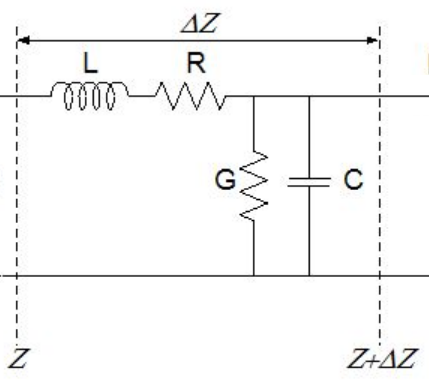
So let's start with transmission lines. At the left you see a circuit diagram for a "tiny section" of a transmission line. It's important to understand what this "tiny slice" thing is all about. Obviously, a transmission line such as a coaxial cable or a ladder line isn't a collection of little inductors, capacitors, and resistors. It's a continuous thing, that is completely uniform all along its length. However, you can think about a transmission line using this circuit model, and you just imagine that the little components are so small and so densely packed that you can't discern them in any sort of individual way.
Ok, so how should you think about these components then? Well, some specific length of transmission line does have a resistance, and an inductance, capacitance, and conductance. It actually looks electrically a lot like that picture over there, for some values of the components. A piece of transmission line has four terminals, just like the circuit in that picture does. If you double the length of your section, you will double all of the numerical parameters. So, the best way to think about the parameters that characterize a given transmission lines is in a "per unit length" sense. A resistance per unit length, an inductance per unit length, and so on.
So, if you hooked a battery and a switch to the left-side terminals of that circuit and closed the switch, you probably already have an idea what to expect. The capacitor initially has zero voltage, so the full voltage of the battery will be applied across the series inductance and resistance. Current will start to ramp up in the inductor; as soon as it does the resistor will start to produce a growing voltage drop, and the capacitor will begin to charge.
The important thing to remember is that there is another copy of this circuit connected to its right-side terminals, so as soon as that first capacitor begins to charge, the whole process will start over again, one circuit copy to the right. And then as that second cap begins to charge, the process will begin again, this time for the third copy of the circuit. And so on. There is a slight difference between copy 1 and copy 2, because when you closed that switch the full battery voltage appeared as a step change, whereas that first capacitor (and all the other caps right on down the line) charges up gradually.
The key thing to understand from this is that nothing happens instantly at right side when you first turn on the switch. Even if you assume the battery voltage appears right away, it takes time for the effects to move their way down the line. If there were no G elements in the transmission line model, you'd expect all of the capacitors, no matter how long your section was, to eventually charge up to the battery voltage. Those conductance elements, though, will each steal a little of the voltage, so in real life the voltage will gradually drop along the line, even at steady state, until you can't detect it any more.
In steady state, if you could measure the voltage all along the line, you'd see the full battery voltage right at the battery, almost zero "a long way" down the line, and in between the voltage would smoothly drop. The battery would deliver some current I to the line. The current would pass through the first R, resulting in a small voltage drop. But the next R would have a smaller drop, because some of the current returned to ground through the first G. So the voltage would drop less and less rapidly as you move along the line, as the current continuing down the line grows smaller.
So, we just got a feel for what would happen to a transmission line in a very simple situation. In our hobby, though, our transmission lines have RF signals from our transceiver coming in one end and reflected energy from our antenna coming in the other end - it's a lot more complicated than just throwing a switch on a battery. But don't worry - we're going to get there - this was just a starting point.
If you're just getting started with all this, you may have blinked when I mentioned reflections. That's ok - we're going to dig into that right now. For a little while, forget about the R's and the G's; just imagine that you've got some perfect transmission lines that have only inductance and capacitance per unit length (wow - wouldn't that be groovy?). Let's go back to our battery and switch experiment, and assume we close the switch into some routine length of our line. It might be a hundred feet, say, and at the far end there's... nothing. So those last to terminals are just haning there in the air.
So, our voltage pulse is going to work it's way down that line, making current flow into each new section. Until it comes to the end. There's nowhere there for any current to go, so as you might expect that last capacitor will charge up faster than the ones before it have, because it's not losing any of its charge to more transmission line beyond it. In this idea case, eventually all of the caps will charge up to the battery voltage. But remember, there's still current flowing in all of the inductors, so that last capacitor is going to keep right on charging up. As soon as its voltage exceeds the voltage of the capacitor to its left, the current coming into it will start to drop. When that happens, the second cap from the right end has more current coming in than going out, so it will start to overcharge too.
Eventually you wind up with a lot of excess voltage down at the far end of the line, and that's going to turn the current around and make it flow back the other way. That, my friends, is our first reflection. This shouldn't surprise you - we have charged up all those inductors and capacitors in that piece of (ideal) transmission line. We took out the energy dissipating bits of it for this thought experiment. There's energy in there, and there's no where for it to go. It can't just vanish. So what happens is that it just bounces off the far end and heads right back toward the left. If we opened the switch before the reflected wave got back to the left end, then there would be nowhere for the energy to go on that end either, and it would just zip back and forth, from end to end, forever. In a real line, of course, the losses would gradually eat it all up.
What if the far right end of the line was shorted, instead of open? Well, a short circuit still doesn't dissipate any energy. You'd still get a reflection. It would just be of the opposite polarity from the open circuit reflection. In fact, you don't have to have an open or short circuit to get a reflection. you just have to have a change. It could be caused by attaching any load whatsoever out there that "looked different" (looking into its terminals) than the transmission line. It could be a resistor, or another piece of (different) transmission line. Or it could be an antenna.
Ok, so this is really enough chit-chat. This is what goes on in these things. This same business happens everywhere in your setup where the nature of the path the signal has to travel changes. It even happens in your antenna. If your antenna is nicely made for the frequency your driving it with, then none of the energy that goes in comes back out. It all either heats the antenna up or is broadcast. This is what you want. But that only happens at that one special frequency (or its harmonics). At other frequencies, some energy is bounced right back out of your antenna. To get to your antenna, the energy has to travel up the feed line. If the feedline and antenna are well matched, it flows right on into the antenna - if they're not, then some of it bounches back from the feedline/antenna junction. That's the story. It's our job to understand all of this well enough to manage it and get as much power as we possibly can launched out into free space, where we want it.
This is what we'll turn our attention to now. We'll shift gears a little and stop thinking at the "micro-level" of the transmission line and start thinking in terms of "whole system" parameters. And we'll wind up writing some Python programs to help us get a grip on all of this.
Ok, so now that we've "gotten a feel" for what goes on in transmission lines at the detailed level, what's next? Well, first of all, we don't drive our transmission lines with batteries and switches. In theory we could, but most of us could wiggle that switch at RF frequencies. And we'd get square waves instead of sine waves, so a lot of harmonic noise would go out. We drive our transmission lines with sinusoidal waves. Also, our lines are very short compared to length of time we transmit, so the line gets chock full of our incoming energy, reflections from all the impedance discontinuities, and so on. We need to get our hands on the "total effect" of all of that.
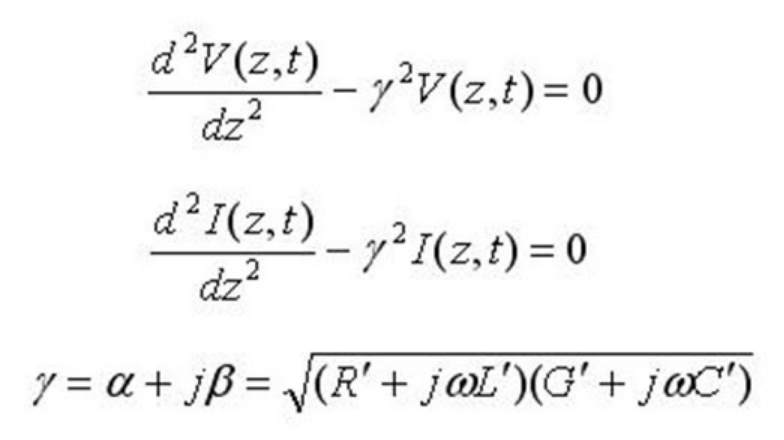
In the stuff above, we only thought about transmission lines as a long chain of discrete components. This is a perfectly legitimate way to think about them, but to get practically useful results you'd need to have a lot of copies of that little circuit, and you sure wouldn't be solving the whole circuit by hand. You could do it on a computer, and if you used enough copies you'd get correct answers. But that's not how RF engineers do it. It turns out that "in the limit" of many many small circuits, the whole massive set of equations can be condensed into equations of a different form, called (logically), the transmission line equations. One form of these equations appears over on the left.
This is where things start getting scary for a lot of people. But don't fret - we're not going to actually solve those equations. They're equations referred to by mathematicians as differential equations, which just means that they tell you how fast various values change, given the actual values at any given time. In this case they tell us how fast the voltage or current changes, at any given spot along the transmission line and at any given time. Well, they actually tell us how fast the change of voltage or current is changing, but it leads to knowing the voltage and current everywhere all the time just the same.
Fortunately, if we neglect a transmission line's losses then the solution of these equations turns out to be very, very simple. Whatever voltage pattern you apply to one end of the line just moves down the line, at some speed that depends on the geometry and materials of the line. It doesn't change shape - it just "slides down the line." So if you hook a transmitter up to a line and key it on, say, 7.1 MHz, a 7.1 MHz sine wave will just glide along the line toward the other end. It glides pretty fast - not at the speed of light, but somewhere up in that neighborhood.
If you put signals into both ends of a transmission line, then each signal slides toward the other end. Eventually they meet, and they simply add - transmission lines are linear. We don't normally drive transmission lines from both ends, but it turns out that reflections behave exactly the same way as signals that we manually put in the other end, so we wind up dealing with waves going both ways anyway.
What about those losses we "ignored" to get to that simple solution? If you want the perfect solution, you can't ignore them. And we want to know about our losses anyway. But it turns out that for practical work we can still work with the ideal solution and then just calculate our total losses after the fact. This isn't exactly right, but it winds up being close enough for our purposes, and we save a lot of work doing it that way. So that's how we'll approach it.
You may be wondering about one other thing at this point. What about out there on the antenna? We're interested in that too - not just the transmission lines. It turnsout the same ideas apply to the antenna too. The antenna terminals represent a "change" within our system, and the tips of our antenna elements represent another "change." In fact, the antenna tips behave like an open circuit, so we get a full reflection there that enforces a zero current condition. So we're going to include that in the model we develop as well.
So, here's what our model is going to include:
You'll find that this model will cover 99% of the things you ever want to do, and hopefully I'll present all of this well enough that should you need more (t-line 3, tuner 3, etc.) you'll be able to modify our work to cover that need.
So, what's a tuner? That's just a little circuit, made of discrete inductors and capacitors (and resistances / conductances too, since our components aren't perfect) that we stick in between two pieces of a model like this to "match them together." The idea is to take a junction that would by itself result in a reflection, and suppress that reflection. A proper tuner can make two mismatched elements look like one smooth element. One of the things we'll want to be able to do is design tuners, so we need to capture them in our model somehow.
When we run our transmitter, we're sending sinusoidal waves out its antenna connector. Sure, they may have a time-varying amplitude, or frequency, or phase - after all, we've got to modulate them somehow in order to put any intelligence into our signals. But a basic understanding of what's going on out there beyond the antenna connector is all about how the gear responds to sinusoids. We've already talked about how our transmitters are on for "long time" compared to how long it takes energy to get from the transmitter to the tips of the antenna (and back and for many times, in fact). So we need to understand what happens out there when we hit fill it all up with sinusoidal RF energy.
So, our transmitter sees some kind of load. The voltage the transmitter produces is a sinusoid - it has an amplitude and a phase (which we can call zero if we want to). In response to that sinusoidal voltage, a sinusoidal current flows. It also has an amplitude and a phase - and that current phase could be non-zero. We can represent both the voltage and the current as complex numbers - the magnitude of the number is just the amplitude and the angle of the number is the phase. We're not going to dwell on it, but it's possible to divide one complex number by another, and if we divide the voltage number by the current number, we will get a result. That result is the impedance seen by the transmitter.
We want to design our whole system - antenna, feedline structure, and tuners, so that the transmitter sees a purely resistive 50 ohm load. We want the current the transmitter delivers to be in phase with the voltage the transmitter produces. So we want our entire system, from the transmitter antenna connect all the way out, to present a 50 ohm impedance. To get our arms around this, we need to start with the antenna and work our way back.
Ok, let's focus on the antenna. We can apply the same reasoning to the terminals of the antenna. The system up to there applies a voltage to the antenna (a sinusoid), and that voltage causes a current to flow into the antenna (also a sinusoid). The current may or may not have the same phase as the voltage. When it does, the antenna offers a purely resistive load to the rest of the system, and that's resonance again. Resonance is good. In any case, that antenna has an impedance.
So let's say our antenna has some impedance, that we'll call Z. What if we now attach a transmission line to it, and drive it through that line instead of directly? It turns out that can change the impedance that we see. That shouldn't be too surprising - if you add components to an electric circuit you shouldn't expect it to behave the same. In this case, it's important for us to understand exactly how the transmission line changes things.